| How to Design Built | 您所在的位置:网站首页 › member design › How to Design Built |
How to Design Built

Sometimes, I-beam sections or girders are built up by welding structural steel plates together. This is usually done when the section required is so heavy that it cannot be picked from the standard sections available, or when the section required is not available with local manufacturers or dealers. The difference between hot-rolled I-section and welded steel sections is shown in Figure 1. The design of a built-up beam (plate girder) involves the selection of adequate individual section sizes, weld sizes, and stiffeners (if required), and verifying their performance as a composite whole in satisfying ultimate and serviceability limit state requirements. 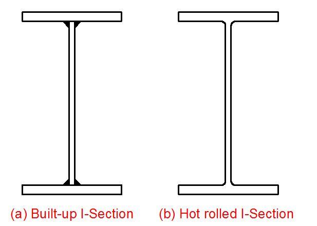 Figure 1: (a)Built-up I-beam (b) Hot rolled I-section
Design Example of Built-Up Beams Figure 1: (a)Built-up I-beam (b) Hot rolled I-section
Design Example of Built-Up Beams
Ghosh (2010) presented an example of the design of a welded-plate girder for a crane gantry in an iron melting workshop/industry. The example has been reproduced here to show how to design welded-plate girders according to the requirements of EN 1993-1-1:2005. Design Forces Ultimate design vertical moment = Mvu = 29515 kNmUltimate design vertical shear force = Vvu = 6282 kNUltimate design horizontal moment = Mhu = 601 kNm Maximum ultimate horizontal longitudinal tractive force = 312 kNSpan of girder = 24 m Design of sectionThe section will be designed as a welded-plate girder. Eurocode 3, Part 1-1 (Eurocode, 2005) will be followed. The tables and figures referred to below can be found in Annex A of the Eurocode (Appendix B of this book), except where otherwise mentioned. 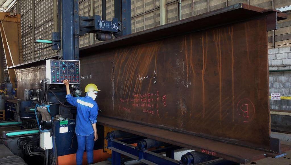 Figure 2: Huge welded I-Section Figure 2: Huge welded I-Section
Design strengthBy referring to Table 3.1 of Eurocode 3 (“Nominal values of yield strength fy and ultimate tensile strength fu for hot-rolled structural steel”), the design strength (fy) in the ULS method of design for the flanges and web can be obtained; its value varies with the thickness of plate considered. In our case, we adopt steel grade S275 with a design yield strength fy = 275 N/mm2. So, for a nominal plate thickness t ≤ 40 mm, fy = 275 N/mm2, and for t ≤ 80 mm, fy = 255 N/mm2. If the design strength of the web fyw is greater than the design strength of the flange fyf, then the design strength of the flange should always be used when considering moments or shear. Initial sizing of sectionThe dimensions of the webs and flanges are assumed to be as given below. Overall depth of girder = h. The depth should be chosen to limit the allowable deflection. In practice, the overall depth should normally be taken to be between 1/10 and 1/12 of the span. In our case, we assume the overall depth h = 1/10 of span = 23.4/10 = 2.34 m = 2340 mm. We assume an overall depth h = 2500 mm (as the girder is subjected to high dynamic wheel loads). Depth of straight portion of web (d) d = h − (2 × size of weld) − (2 × thickness of flange )= 2500 − 2 × 12 (assumed weld size) − 2 × 55 (assumed) = 2366 mm. Breadth of flange (b) The breadth of the flange should be at least 1/40 to 1/30 of the span in order to prevent excessive lateral deflection. In our case, we assume a breadth b = 1/30 of span = (1/30) × 23.4 = 0.78 m, say 0.9 m = 900 mm. Thickness of web (tw)Several tests have shown that the web does not buckle owing to diagonal compression when the ratio d/tw is less than 70, if the web is not stiffened by a vertical transverse stiffener. Referring to Table 5.2 (sheet 1) of Eurocode 3, Part 1-1, the minimum thickness of web required to avoid buckling of the compression flange in the ULS design method with an unstiffened web is as follows. For class 1 classification,d/tw ≤ 72ε, whereε = stress factor = (235/fy)0.5 = (235/255)0.5 = 0.96;d/tw = 2366/tw = 72 × 0.96Therefore tw = 2366/(72 × 0.96) = 34 mm With a stiffened web and a spacing of transverse stiffeners a ≤ d,tw ≥ (d/250)(a/d)0.5.Assuming a spacing of stiffeners a = 2366 mm;tw = 2366/250 × (2366/2366)0.5 = 10 mm.We assume tw = 30 mm. Thickness of flange (tf)The minimum thickness of the flange required to limit the outstand of the flange is calculated as follows. The approximate flange area required is given by; Af = Mvu/(hfy) = (29515 × 106)/(2500 × 255) = 46298 mm2Assuming the width of the flange b = 900 mmtf = 46298/900 = 51.4 mm. We, therefore, assume tf = 55 mm Classification of cross-sectionsReferring to Clause 5.5.2 of Eurocode 3, Part 1-1, the function of cross-section classification is to identify the extent to which the resistance and rotation capacity of the cross-section are limited by its local buckling resistance. In our case, we assume a class 1 cross-section classification without reduction of resistance. Thus, to determine the thickness tf of the flange, we do the following. For class 1 section classification, c/tf ≤ 9ε, where;c = outstand of flange plate = [b − (tw + 2 × 12 (weld size))]/2 = [900 − (25 + 24)]/2 = 425.5 mm.Assuming tf = 55 m,c/tf = 425.5/55 = 7.7 and 9ε = 9 × 0.96 = 8.64 Since c/tf (7.7) < 9ε (8.64), the section satisfi es the conditions for class 1 section classification.So we assume tf = 55 mm. To determine the thickness of the web tw, we do the following;For class 1 section classification, d/tw ≤ 72ε. Assuming tw = 30 mm,d/tw = 2366/30 = 78.9 and 72ε = 72 × 0.96 = 69 < d/tw which does not satisfy the condition. We increase the thickness tw to 35 mm. d/tw = 2366/35 = 67.6 < 72ε (69) which satisfies the condition. So, we assume tw = 35 mm. Thus the initial sizing of the section is as follows: Depth of girder h = 2500 mm. Breadth of flange b = 900 mm. Depth of straight portion of web d = 2500 − 2 × 55 − 2 × 12 (weld size) = 2366 mm. Thickness of web tw = 35 mm. Thickness of flange tf = 55 mm. Design strength with flange thickness 55 mm = fy = 255 N/mm2 Design strength of web with thickness 35 mm = fy = 255 N/mm2Although the design strength of the web is 275 N/mm2 for 35 mm thickness, the lower value of fy (255 N/mm2) of the flange should be considered in calculations for moments and shears. 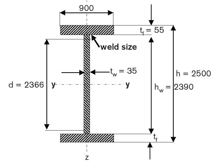
Moment capacityTotal maximum ultimate vertical design moment = Mvu = 29515 kNmTotal maximum design shear = Vu = 6281 kN The moment capacity should be calculated in the following way.When the web depth-to-thickness ratio d/tw ≤ 72ε, it should be assumed that the web is not susceptible to buckling, and the moment capacity should be calculated from the equation; Mrd = fyWpl provided the shear force VEd (Vvu) ≤ 0.5Vpl,rd (shear capacity), where Mrd = moment capacity,Wpl = plastic section modulus Vpl,rd = shear capacity. In our case, d/tw (67.6) < 72ε (69.1).Thus, the web is not susceptible to buckling. The ultimate shear force (Vvu) should also be less than half the shear capacity (Vpl,rd) of the section. Referring to equation (6.18) of Eurocode 3, Part 1-1; Vpl,rd = Av[fy/(3)0.5]/γMo whereAv = shear area = dtw + (tw + 2r)tf = 2366 × 25 + (25 + 2 × 12) × 50 = 61600 mm2 Referring to Clause 6.1, γMo = partial factor = 1.0, and fy = 335 N/mm2 (because tf > 40 mm).Therefore plastic shear capacity Vpl,rd = 61600 × [335/(3)0.5]/1.0/103 = 12669 kNand 0.5Vpl,rd = 12669/2 = 6335 kN > Vvu (6281 kN). Thus, Vvu (6281 kN) < 0.5Vpl,Rd (6335 kN). So the section satisfies the conditions. Since the web is not susceptible to buckling, and the lowest shear value in the section is less than half the shear capacity of the section, the moment capacity for this class 1 compact section should be determined by the “flange only” method. In this case, the whole moment will be taken up by the flanges alone and the web takes the shear only. Therefore moment capacity of section My,Rd = fyAfhs where;Af = area of compression flange = b × tf = 900 × 55 = 49500 mm2 hs = depth between centroids of flanges = 2500 − 55 = 2445 mmfy = 255 N/mm2 Therefore; My,Rd = 255 × 49500 × 2445/106 = 30862 kNm > MEd (Mvu) (29515 kNm). Satisfactory Alternatively, referring to Clause 6.2.5, the moment capacity of the section may be expressed by the following equation: Mpl,Rd = Wplfy/γMo The plastic modulus is calculated to be 1.71008 x 108 mm3Mpl,Rd = Wplfy/γMo = [(1.71008 x 108 × 255)/1.00] × 10-6 = 43607 kNm where Wpl is the plastic modulus of the section. As the section assumed is built-up welded and of high depth, no rolled I section is available of this depth. The plastic modulus for the assumed depth can be calculated. So the above equation can only be used when the assumed section is manufactured industrially by welding. In addition, the top flange is also subjected to a stress due to the horizontal transverse moment caused by horizontal crane surges. Therefore, the “flange only” method is suitable in our case. The horizontal transverse ultimate moment Mhu is equal to 601 kN m. This transverse horizontal moment is resisted by a horizontal girder formed by the connection of the 6 mm plate (acting as a web) of the walking platform (Durbar), between the top flange of the main plate girder and the tie beam at the walking-platform level. Distance between centre line of plate girder and the tie beam = hz = 2.5 m Horizontal moment of resistance = Mz,Rd = fyAfhzwhere Af = area of top flange = 900 × 55 = 49500 mm2. ThereforeMz,Rd = 255 × 49 500 × 2500/106 = 31556 kNm > Mhu (601 kNm) Referring to the criterion based on the quantity; [My,Ed/My,Rd]α + [Mz,Ed/Mz,Rd]β where α and β are constants, which may conservatively be taken as unity. This quantity is equal to[29515/30862] + [601/31556] = 0.95 + 0.02 = 0.97 < 1 Satisfactory Therefore we adopt the section for the welded-plate girder. For other design checks such as buckling and stiffness design, see Ghosh (2010). Source: Ghosh K. M (2010): Practical Design of Steel Structures. Whittles Publishing, UK |
【本文地址】